8 Security Aspects
Requisitos de finalización
8.4 Enhancements in LTE and LTE-A
In
3G there are still some security problems, as the IMSI may be sent in clear
text, and the transmission of the IMEI is not protected. The user can also be
enticed to camp on a fake BS (e.g. with high transmit power). Then it is out of
reach of paging by its network. If encryption is disabled, which is still
allowed, a man-in-the-middle attack can be played.
UMTS security enhancements have been mutual authentication, integrity keys, public algorithms, deeper encryption, and longer key length. The LTE architecture in addition is flat and separates control plane and user plane, uses eNode Bs replacing Node B/RNC, uses an all IP-network, interworking with legacy and non 3GPP networks. The characteristics of LTE security are therefore, reuse of UMTS authentication and key agreement (AKA), extended key hierarchy, possibility for longer keys, better protection for backhaul, and integrated interworking security for legacy and non 3GPP networks.
The LTE security architecture handles different sets of security features:
Network access security comprises the set of security features that provides the UEs with secure access to the EPC and to protect against various attacks on the radio link. Network domain security is the set of security features that protects against attacks on the wire line network and enables nodes to exchange signaling data und user data in a secure manner. User domain security is the set of security features that provides a mutual authentication between USIM and ME. Application domain security is the set of security features that enables applications in the UE and in the provider domain to securely exchange messages. Non 3GPP domain security is the set if features that enables the UE to securely access to the EPC via non-3GPP access networks and provides security protection on the radio access link (e.g. IEEE 802.11).
Device and network authentication are handled by authentication and key agreement. The AKA protocol is used for devices to authenticate with the carrier to gain network access. Cryptographic keys needed to encrypt calls are generated upon completion of the AKA protocol (Figure 8-5).
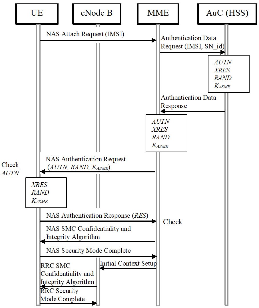
Figure 8-5: Authentication in LTE (AKA).
The security in the handover process for intra E-UTRAN mobility is as follows: Current eNode B and target eNode B are managed by the same MME. A new key management mechanism is designed with different ways to derive the new eNode B keys based on vertical or horizontal key derivations. After an initial access authentication, MME and UE shall derive a key KeNB and a next hop (NH) parameter from KASME. In the initial setup KeNB is derived directly from KASME and is associated with a virtual NH parameter with NH chaining counter (NCC) zero. The UE and the eNode B use KeNB to secure the communication on the air interface. In handovers, a new session key K*eNB used between UE and target eNode B is derived from either the active KeNB or from the NH parameter (Figure 8-6).
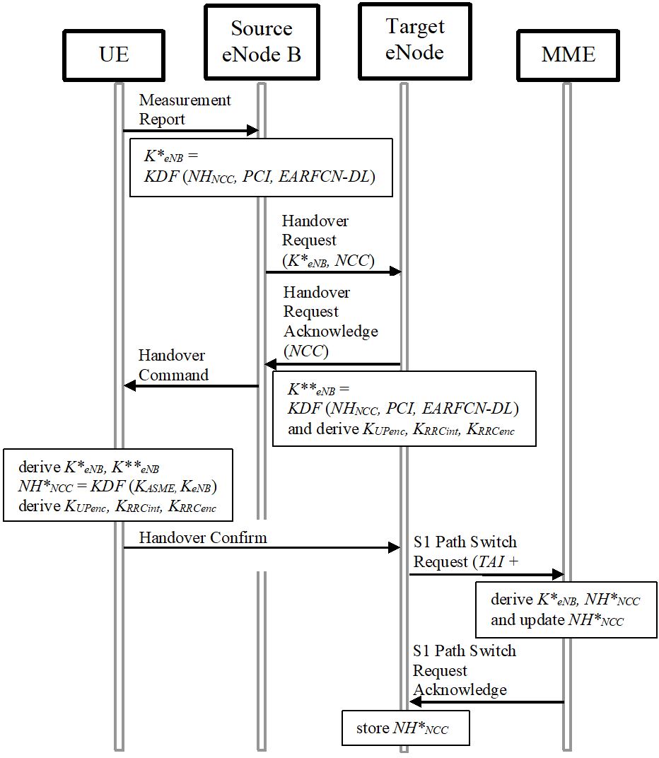
Figure 8-6: Inter eNode B Handover in LTE (with KDF: key derivation function).
The mobility between E-UTRAN and UTRAN/GERAN is a little different. A handover from E-UTRAN starts with UE and MME deriving CK and IK from KASME. Upon receiving CK’||IK’ with KSI’ from MME, the target SGSN and the UE shall replace all stored parameters CK, IK, KSI with CK’, IK’, KSI’. In a handover from UTRAN/GERAN the target MME and the UE shall derive K’ASME from CK and IK or GPRS Kc received from SGSN. Target MME and UE shall derive KeNB and the corresponding NAS keys according to the key hierarchy of LTE. For mobility with non-3GPP networks several different mobility scenarios between heterogeneous access systems exist in the LTE networks. The UE, the target access network and the PCC will implement a full access authentication procedure before the UE handovers to the new access network.
The current keys are derived by two separate algorithms specified in addition to the NULL algorithm. The length in use is 128 bit but may be extended to 256 bit in the future. The confidentiality protection of NAS/AS signaling is recommended, the integrity protection is mandatory. The integrity key is derived by the algorithm EIA with input COUNT, message, direction, and bearer. It is attached to the original message and the receiver compares it with the values calculated in the receiver. The algorithms are based on SNOW 3G stream ciphers with a keystream provided by linear feedback shift registers (LFSR) and a finite state machine (FSM). It therefore differs from KASUMI used in UMTS and allows for low power consumption and low gate count implementation in hardware. Alternatively, an AES block cipher is defined as a second algorithm, and a third algorithm is based on Chinese ZUC stream cipher. The key hierarchy is deeper than in LTE: Based on the secret key K (128 bit) CK and IK will be the next level, followed by KASME (256 bit) derived from CK and IK. From KASME there are derived KNASenc and KNASint protecting NAS and KeNB. From the latter KUPint, KUPenc, KRRCint, KRRCenc for protecting UP traffic and RRC are calculated.
In LTE the backhaul shall also be protected. The S1 interface from E-UTRAN to S-GW is confidentiality protected using hardware appliances, security gateways and IP-tunneling.
In general LTE is markedly more secure than its predecessors, but a lot of the security mechanisms are only optional. A problem is also posed by the handovers to and from non-3GPP networks.
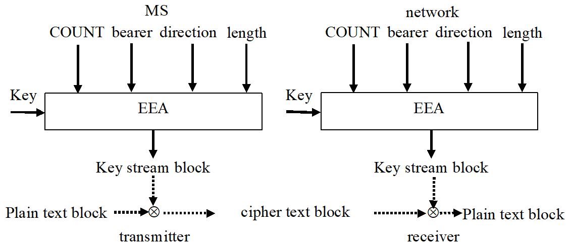
Figure 8-7: Ciphering in LTE.
UMTS security enhancements have been mutual authentication, integrity keys, public algorithms, deeper encryption, and longer key length. The LTE architecture in addition is flat and separates control plane and user plane, uses eNode Bs replacing Node B/RNC, uses an all IP-network, interworking with legacy and non 3GPP networks. The characteristics of LTE security are therefore, reuse of UMTS authentication and key agreement (AKA), extended key hierarchy, possibility for longer keys, better protection for backhaul, and integrated interworking security for legacy and non 3GPP networks.
The LTE security architecture handles different sets of security features:
Network access security comprises the set of security features that provides the UEs with secure access to the EPC and to protect against various attacks on the radio link. Network domain security is the set of security features that protects against attacks on the wire line network and enables nodes to exchange signaling data und user data in a secure manner. User domain security is the set of security features that provides a mutual authentication between USIM and ME. Application domain security is the set of security features that enables applications in the UE and in the provider domain to securely exchange messages. Non 3GPP domain security is the set if features that enables the UE to securely access to the EPC via non-3GPP access networks and provides security protection on the radio access link (e.g. IEEE 802.11).
The
LTE security of the network comprises LTE cellular security, LTE handover
security, IMS security, eNode B security, and MTC security.
Device and network authentication are handled by authentication and key agreement. The AKA protocol is used for devices to authenticate with the carrier to gain network access. Cryptographic keys needed to encrypt calls are generated upon completion of the AKA protocol (Figure 8-5).
Figure 8-5: Authentication in LTE (AKA).
The security in the handover process for intra E-UTRAN mobility is as follows: Current eNode B and target eNode B are managed by the same MME. A new key management mechanism is designed with different ways to derive the new eNode B keys based on vertical or horizontal key derivations. After an initial access authentication, MME and UE shall derive a key KeNB and a next hop (NH) parameter from KASME. In the initial setup KeNB is derived directly from KASME and is associated with a virtual NH parameter with NH chaining counter (NCC) zero. The UE and the eNode B use KeNB to secure the communication on the air interface. In handovers, a new session key K*eNB used between UE and target eNode B is derived from either the active KeNB or from the NH parameter (Figure 8-6).
Figure 8-6: Inter eNode B Handover in LTE (with KDF: key derivation function).
The mobility between E-UTRAN and UTRAN/GERAN is a little different. A handover from E-UTRAN starts with UE and MME deriving CK and IK from KASME. Upon receiving CK’||IK’ with KSI’ from MME, the target SGSN and the UE shall replace all stored parameters CK, IK, KSI with CK’, IK’, KSI’. In a handover from UTRAN/GERAN the target MME and the UE shall derive K’ASME from CK and IK or GPRS Kc received from SGSN. Target MME and UE shall derive KeNB and the corresponding NAS keys according to the key hierarchy of LTE. For mobility with non-3GPP networks several different mobility scenarios between heterogeneous access systems exist in the LTE networks. The UE, the target access network and the PCC will implement a full access authentication procedure before the UE handovers to the new access network.
The current keys are derived by two separate algorithms specified in addition to the NULL algorithm. The length in use is 128 bit but may be extended to 256 bit in the future. The confidentiality protection of NAS/AS signaling is recommended, the integrity protection is mandatory. The integrity key is derived by the algorithm EIA with input COUNT, message, direction, and bearer. It is attached to the original message and the receiver compares it with the values calculated in the receiver. The algorithms are based on SNOW 3G stream ciphers with a keystream provided by linear feedback shift registers (LFSR) and a finite state machine (FSM). It therefore differs from KASUMI used in UMTS and allows for low power consumption and low gate count implementation in hardware. Alternatively, an AES block cipher is defined as a second algorithm, and a third algorithm is based on Chinese ZUC stream cipher. The key hierarchy is deeper than in LTE: Based on the secret key K (128 bit) CK and IK will be the next level, followed by KASME (256 bit) derived from CK and IK. From KASME there are derived KNASenc and KNASint protecting NAS and KeNB. From the latter KUPint, KUPenc, KRRCint, KRRCenc for protecting UP traffic and RRC are calculated.
In LTE the backhaul shall also be protected. The S1 interface from E-UTRAN to S-GW is confidentiality protected using hardware appliances, security gateways and IP-tunneling.
In general LTE is markedly more secure than its predecessors, but a lot of the security mechanisms are only optional. A problem is also posed by the handovers to and from non-3GPP networks.
Figure 8-7: Ciphering in LTE.